Experiment
22
Stefan-Boltzmann
Law
1. Introduction
When you
turn on an electric heater you may observe that it has changed its color to red
or orange. At high temperatures all objects emit visible radiation. But when the
heater is set to work at low power, you will not observed any visible
radiation, however you may check that it is working by simple holding your hand
near the burner. In both cases the energy is emitted by the burner, and it is
called radiation.
The Stefan-Boltzmann
law relates the power, P, per area, A, radiated by an object to the absolute
temperature, T, of the object as shown below
P/A = s T4 (1)
where P is
in watts, A is in meter2, T in degrees Kelvin, and the
Stefan-Boltzmann constant s (sigma) = 5.67 10-8 W/m2K4. The law has been found experimentally by J. Stefan and
explained theoretically by L. Boltzmann. This law describes only the total
amount of energy emitted each second by the object, and does not provide any
information about the distribution of energy as a function of frequency.
2. Procedure
In this experiment you will do relative measurements of the power per unit area emitted by a lamp at different temperatures. Since we do not know the surface area of the filament in the light bulb, all measurements will be relative, and we will not be able to determine absolute values of emitted radiation. However, from your data you will be able to test the Stefan-Boltzmann law.
Set up the equipment as shown in Fig. 1. The voltmeter should be connected directly to the binding posts of the lamp. The sensor should be at the same height as the filament of the lamp, with the front face of the sensor approximately 6 cm away from the filament. There should be no objects other than the lamp close to the sensor. In order to find the emitted energy you will use a radiation sensor. It is a miniature thermopile that produces a voltage proportional to the intensity of the radiation. It measures radiation in the infrared and visible region, and the
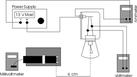
Fig. 1. Experimental set-up.
voltage produced ranges from 1 microvolt up to about 100 millivolts.
The sensor is mounted on a stand and its position should be fixed during
the experiment. The sensor is protected by a
shutter that can be open by sliding the shutter ring back or forward. It can
also be open by momentarily pressing the horizontal arm of the shutter. After
you record the data release the shutter. The shutter should be closed when the
measurements are not being taken. Please note, that when closing or opening the
shutter it is possible to change the sensor position and it may affect your
measurements.
The source of radiation in
this experiment is a 12 V lamp. By adjusting the power of the lamp, filament
temperatures up to 30000C can be obtained. The filament temperatures
can be determined by carefully measuring the voltage and current flowing
through the lamp. From the Ohm's law you may find the resistance of the
filament
R = V/I (2)
For small temperature changes the temperature of the tungsten filament can be calculated from the equation relating the change in the resistance to the increase of the temperature
T = Troom + (RT
- Rroom)/aRroom (3)
where Troom is the reference
temperature, usually room temperature, Rroom is the resistance at
the reference temperature, and a is the temperature coefficient of resistivity. The temperature
coefficient of resistivity for tungsten is a = 4.5 10-3 K-1.
Eq. 3 is true only for small temperature changes, and for large
temperature differences, as in this experiment, the temperature of the filament
can be estimated using experimental data
on resistivity of tungsten listed in Table 1 and depicted in Fig. 2. Use the
following procedure.
a)
Accurately
measure the resistance Rroom of the tungsten filament. Accuracy is
important. A small error in Rroom will result in large errors in
your estimation of the filament temperature. It is possible that the lab
assistant measured this value for you and recorded on the lamp’s stand. Use
that value for Rroom.
Table. 1.
Resistivity of tungsten as a function of temperature
|
R/R300K |
Temp [K] |
Resistivity mW cm |
R/R300K |
Temp [K] |
Resistivity mW cm |
R/R300K |
Temp [K] |
Resistivity mW cm |
R/R300K |
Temp [K] |
Resistivity mW cm |
|
1.0 |
300 |
5.65 |
5.48 |
1200 |
30.98 |
10.63 |
2100 |
60.06 |
16.29 |
3000 |
92.04 |
|
1.43 |
400 |
8.06 |
6.03 |
1300 |
34.08 |
11.24 |
2200 |
63.48 |
16.95 |
3100 |
95.76 |
|
1.87 |
500 |
10.56 |
6.58 |
1400 |
37.19 |
11.84 |
2300 |
66.91 |
17.62 |
3200 |
99.54 |
|
2.34 |
600 |
13.23 |
7.14 |
1500 |
40.36 |
12.46 |
2400 |
70.39 |
18.28 |
3300 |
103.3 |
|
2.85 |
700 |
16.09 |
7.71 |
1600 |
43.55 |
13.08 |
2500 |
73.91 |
18.97 |
3400 |
107.2 |
|
3.36 |
800 |
19.00 |
8.28 |
1700 |
46.78 |
13.72 |
2600 |
77.49 |
19.66 |
3500 |
111.1 |
|
3.88 |
900 |
21.94 |
8.86 |
1800 |
50.05 |
14.34 |
2700 |
81.04 |
26.35 |
3600 |
115.0 |
|
4.41 |
1000 |
24.93 |
9.44 |
1900 |
53.35 |
14.99 |
2800 |
84.70 |
|||
|
4.95 |
1100 |
27.94 |
10.03 |
2000 |
56.67 |
15.63 |
2900 |
88.33 |
b) Turn on the power supply. Set the voltage, V, to each of the settings listed in Table 2. When filament is hot, measure the voltage and current in the filament and find the resistance RT. Record the radiation, RAD, the reading on the millivoltmeter.
Important: The voltage to the lamp should never exceed 13 V. Make each reading of the sensor as quickly as possible so that the temperature of the sensor stays relatively constant.
c) Divide RT by Rroom
to obtain the relative resistance.
d)
Using the value
for the relative resistance of the filament, use Table 1, or associated graph,
to determine the temperature of the filament and record the result in Table 2.
3. Report
Calculate T4 for each value of T and enter your results in Table 2.
On a separate sheet of paper, construct a graph of RAD versus T4.
Use RAD as your dependent variable (y-axis).
In the introduction discuss the Stefan-Boltzmann
law. It is true only for ideal,
perfectly black body radiation. A black body is any object that absorbs all the
radiation that strikes it. Is the filament of the lamp a true black body? Also, in the introduction list different units of
energy commonly used to measure electric power, such as erg, Joule,
kilo-watt-hour, electron-volt, calorie, BTU (British thermal unit) and show
relationships
In the
discussion section answer the following questions.
1. Is your graph a straight line? Is it
straight over the entire range of measurements?
2.
What sources of
thermal radiation, other than the lamp, might have influenced your measurements?
What effect would you expect these sources to have on your results?
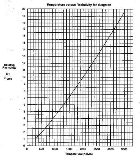
Fig. 2.
Temperature dependence of relative resistivity for tungsten.
Table 2.
Experimental data
|
Potential [V] |
Current [A] |
Radiation, RAD [mV] |
R [ohms] |
Temperature [K] |
T4 |
|
1.0 |
|||||
|
2.0 |
|||||
|
3. |
|||||
|
4.0 |
|||||
|
5.0 |
|||||
|
6.0 |
|||||
|
7.0 |
|||||
|
8.0 |
|||||
|
9.0 |
|||||
|
10.0 |
|||||
|
11.0 |
|||||
|
12.0 |